Check if the displayed dimension is 50mm. Try verticalHorizontal or Aligned.
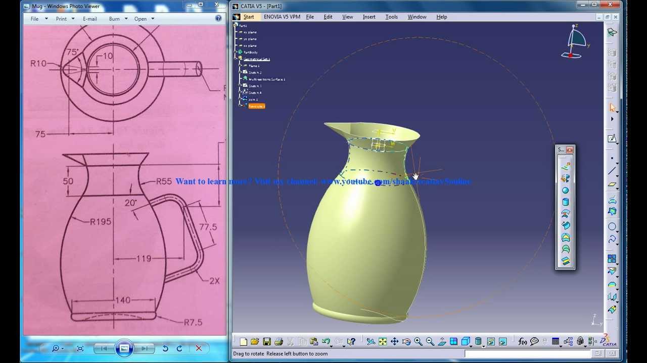
Catia V5 Tutorials Wireframe And Surface Design Rebuild A Mug Part 2 Youtube
It is a three dimensional modeling tool.

. 52 of all the cars built in 2000 were designed with CATIA. Advanced Surface Design Version 5 Release 20 Student Guide Revision 10 June 2011 ASCENT - Center for Technical Knowledge CATIA. To bring back any hidden dimension or annotation in your drawing youll need to activate the HideShow Annotation command found under View HideShow Annotations.
CATIA 3D product development is now used by 22 of the top 30 global automotive. The Line-up dialog box appears. Just select one or two features in the same view to get a dimension.
22 Jan 2016 0604 AM i am BE finalsurface drawing need for practise in CATIA V5 R20. If you select one or more dimensions you can Right Click on a dimension and select Hide. CATIA figures out the view.
Drag to select the callout radius and click a point to end the selection. After you choose the material for you part you can very easy track your dimensions. The Windows Philosophy c.
76 Hrs Chapter 1. Introduction to Generative Shape Design CATIA is a robust application that enables you to create rich and complex designs. First lets hide some dimensions.
More than all other CAD design engineering products combined together. PLM in Practice e. With this density the weight of a part can be measured in CATIA.
PLM Product Life Cycle Management d. CATIA to know the design intent. CATIA is a French designed Computer Aided Design CAD tool.
If its not what U were looking for then Please elaborate ur Question. Then CATIA calls to Select a dimension or geometry as reference to line-upin the bottom left corner of the screen. RMBPropertiesDimension Text tabunder Associated Texts place the in the box to the left of the text Main Value and the in the box to the right.
How features affect. To get dimensions. First you want to make a drawing and then create various views of the the assembly front side auxillary section etc.
Dimensionpng Upvote 0 Upvoted 1 Downvote 0 Downvoted 1 santhoshp Answered on 21 Aug 2012 0918 AM. The Functional Tolerancing and Annotation FTA workbench in CATIA allows for a user to overlay information that would normally be found in a separate drawing file directly into the 3D part or product file. It is similar in use to Autocad NX Formerly known as UG Pro-E.
What is CATIA V5. If you hold down the Ctrl key while you select. The variables are usually called parameters of a point on the surface and denoted through U and V while the scalar functions represent the mapping for each point of the surface between the Cartesian coordinates usually called X Y Z and the.
You can split a body with a plane face or surface. Many believe that this capability is the beginning of the end for. Once you have the views you can add whatever dimensions you need.
CATIA V5 Surface Design CATIA V5 Training Foils Version 5 Release 19 A ug st 2 08 EDU _CAT N V5S FI R19. CATIA V5 the New Generation b. Introduction to Surface Design student guide by covering advanced curve and surface topics.
Create a length dimension on a curve. Click Sketch icon and select yz plane. Hence it is defined by three scalar functions of two variables.
It is very important because each material as you know has a density. CATIA V5 Fundamentals 11 Welcome to CATIA V5 a. October 29 2007 1051 PM in response to James Bishop Hello there In 2D drafting when a length dimension is created Right-click will give you an option of curvelinear.
Advanced Surface Design student guide expands on the knowledge learned in the CATIA. Leveraging the capabilities of Microsoft Excel you can easily control design parameterssuch as dimensions suppression states and materialsthrough cells in a spreadsheet. 14 out of the Top 20 automotive manufacturers use CATIA as their core design system.
6 Answers Hugo Alanis. Dimensions for curves 122 Generative Dimensions. How to display the weight mass center of gravity and surface in CATIA V5.
The dimension will have a curve above the numerical display to indicate what the type is. This tool is used in the design of various objects such as vehicles buildings components etc. First column defines offset of the smallest dimension from the edge.
CATIA V5R16 surface modeling Mouse Tutorial 2A To confirm that the size of the drawing is correct- Click Dimensions icon. A surface is a function from a closed interval of R2 to R3. Click the callout center.
SOLIDWORKS design tables help you to efficiently create and manage model configurations. X 14inThe CATIA V5-6R2015. The other option and the easiest is to use the Manipulators Small red triangles in front and behind the dimension text when it is selected.
If we need to take this a step further within Tools Options Mechanical Design Drafting Dimension setting By default create dimensions on circles to Edge will take care of this in a more permanent fashion. Or go to the main menu Tools Positioning Line-up. CATIA V5R16 Generative Shape Design.
Select all affected dimensions right click and select Line-Up option. To copy and paste the drawing into 3D space-. Advanced Surface Design Version 5 Release 20 Revision 10 Prepared and produced by.
If not we need to enlarge or shrink the drawing into the correct size. Click to generate the detail view. 1 StartShapeGenerative Shape Design 2 To make a Sweep surface-.
Flatness controls how flat a surface must be in order to meet the design requirements. Creating a Detail View Detail View Profile In the Drawing window click Detail View in the Views toolbar Details sub-toolbar. It is not the purpose of this course to teach GDT but.
Once you have your model fully constructed though there comes the question of. CATIA Within PLM f. For example the density of steel is 7860kgm 3.
I need surface modeling drawingsfor my practise. Specifying roughness on multiple surfaces in CATIAs FTA workbench. Select the Dimension - Right Click -DimensionObject - Dimension Representation here U will see few option.
Answered on 22 Jan 2016 0339 PM Hi friend good morning. How do you split in Catia. ASCENT Center for Technical Knowledge 1001 E.
The goal of the course. Need some more info on Drafting. Draw an arcR500 with one end 00 as shown in Fig1 Click Exit to complete Deselect Sketch1 Click Sketch icon.
Hope you found todays CATIA Tip in a Minute or Less to be useful if not just interesting. CATIA V5 Mechanical Surface Designer Advanced Course Curriculum Duration. ADVANCED SURFACE DESIGN ASCENT Center for Technical Knowledge.
Click on the scale line of the drawing.
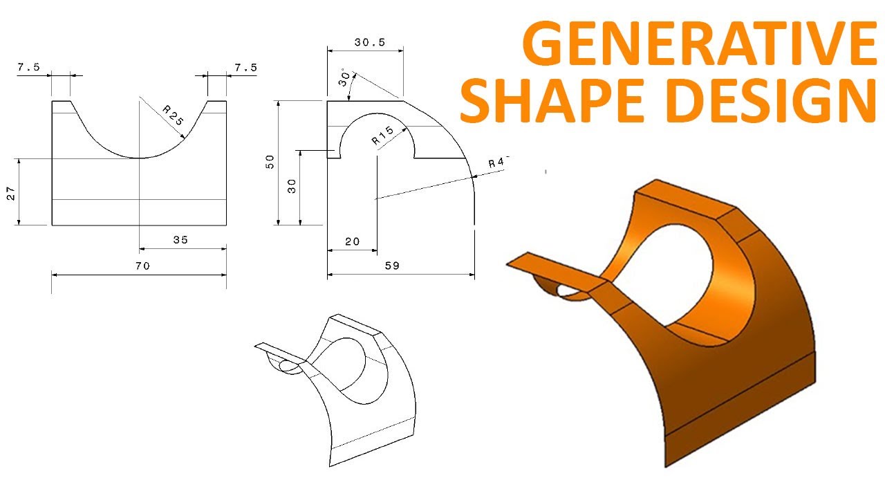
Generative Shape Design 1 Catia V5 Beginner Tutorial How To Use Extrude And Split Youtube

I Need Drawing For Practice In Wireframe And Surface Design Grabcad Questions
Pin On Catia V5 Video Tutorials

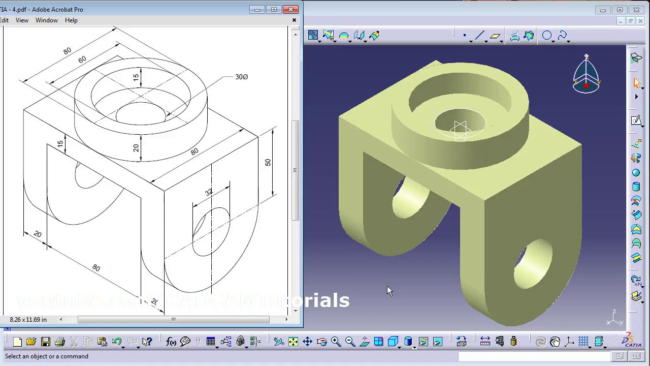
How To Create A Mechanical Part Using Catia Part Design Surface Design Mechanical Design Mechanical Engineering Design
Catia Surface Design Exercises For Beginners 2 Catia Surface Design Tutorial Youtube

I Need Drawing For Practice In Wireframe And Surface Design Grabcad Questions

I Need Drawing For Practice In Wireframe And Surface Design Grabcad Questions

Catia Simple Surface Design For Beginners Youtube
0 comments
Post a Comment